Muller's World
2021-01-18 The Hog 1 Pidal - Yet Another Raspberry Pi Guitar Effects Pedal
Around mid 2019, and after about 15 years of regular use, I'd started having some hardware problems with my Digitech RP-300A effects pedal (footswitches worked intermitently or not at all, expression pedal couldn't do the full range of values...). By early 2020 I decided it was time to move on.
Though I generally thought the Digitech was a great product, I had become a little bit frustrated by some of its limitations and I wanted to try something more. I had a pretty good idea what kinds of features I wanted:
-
Footswitch Configurability. I wanted to be able to punch in specific effects, as well as toggling between programs.
-
Portability. I'd been occassionally playing gigs in NYC in 2019, and I really wanted something that would fit in my gig bag.
-
Open Source Effects. I wanted to be able to use the same effects that I use while recording in a DAW, so that I could recreate my recorded sound live.
-
Expandability. I wanted to be able to hook up other midi controllers and USB interfaces to the device.
The MOD Dwarf ticked most of these boxes, but it didn't look like it would be generally available until at least December of 2020 (and in fact, at the time of this writing, still isn't). So I decided to take a swing at building my own Raspberry Pi based pedal.
What follows is the story of how I did it, presented in the form of a sort of "how to" that others can hopefully immitate. I've been very satisfied with the results, and the software is continuing to evolve. Be warned, if you want to do something similar it will take a bit of time: I'd estimate the whole project took me between 20 and 40 hours over the course of about a month. The materials probably cost under $250 in total, including shipping. There are a couple of special pieces of hardware that I 3D printed, if you don't have access to a 3D printer it shouldn't be too difficult to craft some substitutes. A Dremel rotary tool is extremely helpful for cutting openings in the box.
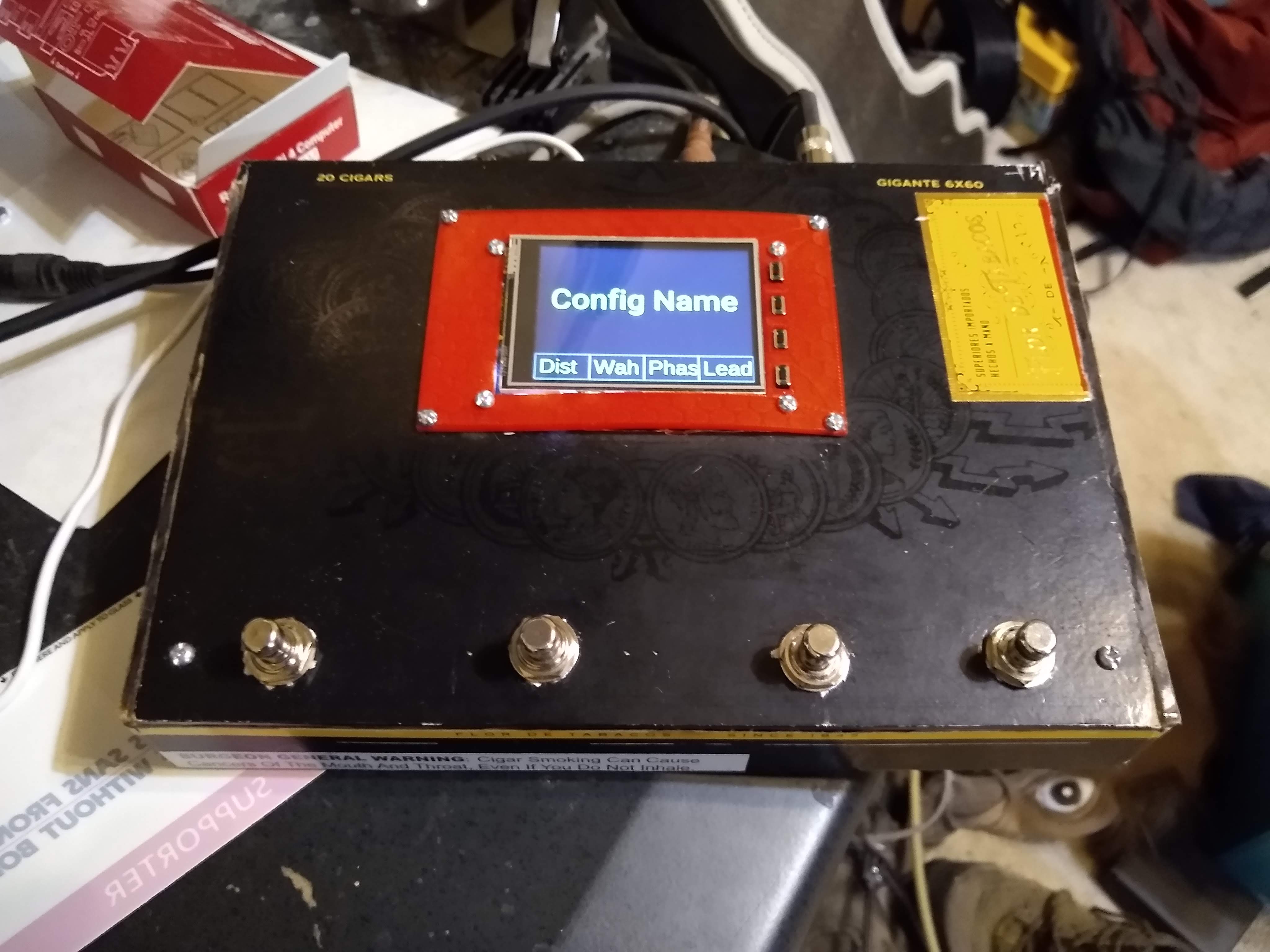
I've dubbed the unit the "Hog-1 Pidal." The "Hog" part comes from my internet handle ("mindhog") and the "Pidal" part is a bad pun on "Raspberry Pi" and "pedal" (I suppose any Pi based effects pedal could be referred to as a "pidal").
So if you're interested, read on! Here's a bad quality video of the unit in action.
- Raspberry Pi Model 4, 2G RAM.
- PiTFT Touchscreen.
- SoundBlaster Play 3 USB Sound Card.
- 4 Heavy Duty Momentary Foot Switches
- 1 Heat Sink
- 1 16G Micro-SD card.
-
5 jumper wires with at least one female end. I strongly recommend the "soft ended" female plugs on these over the hard plastic ones: the soft ends are a little bit bendable, and they're going to need to fit in a fairly tight spot.
- 3 Panel Mount USB Cables
- 1 Panel Mount Ethernet Cable
- 1 USB C Panel Mount Cable
- 1 1/8th inch male/female mono extension cable
- 1 1/4 inch double mono female to 1/8th stereo male adapter cable
- 1 Power Supply
-
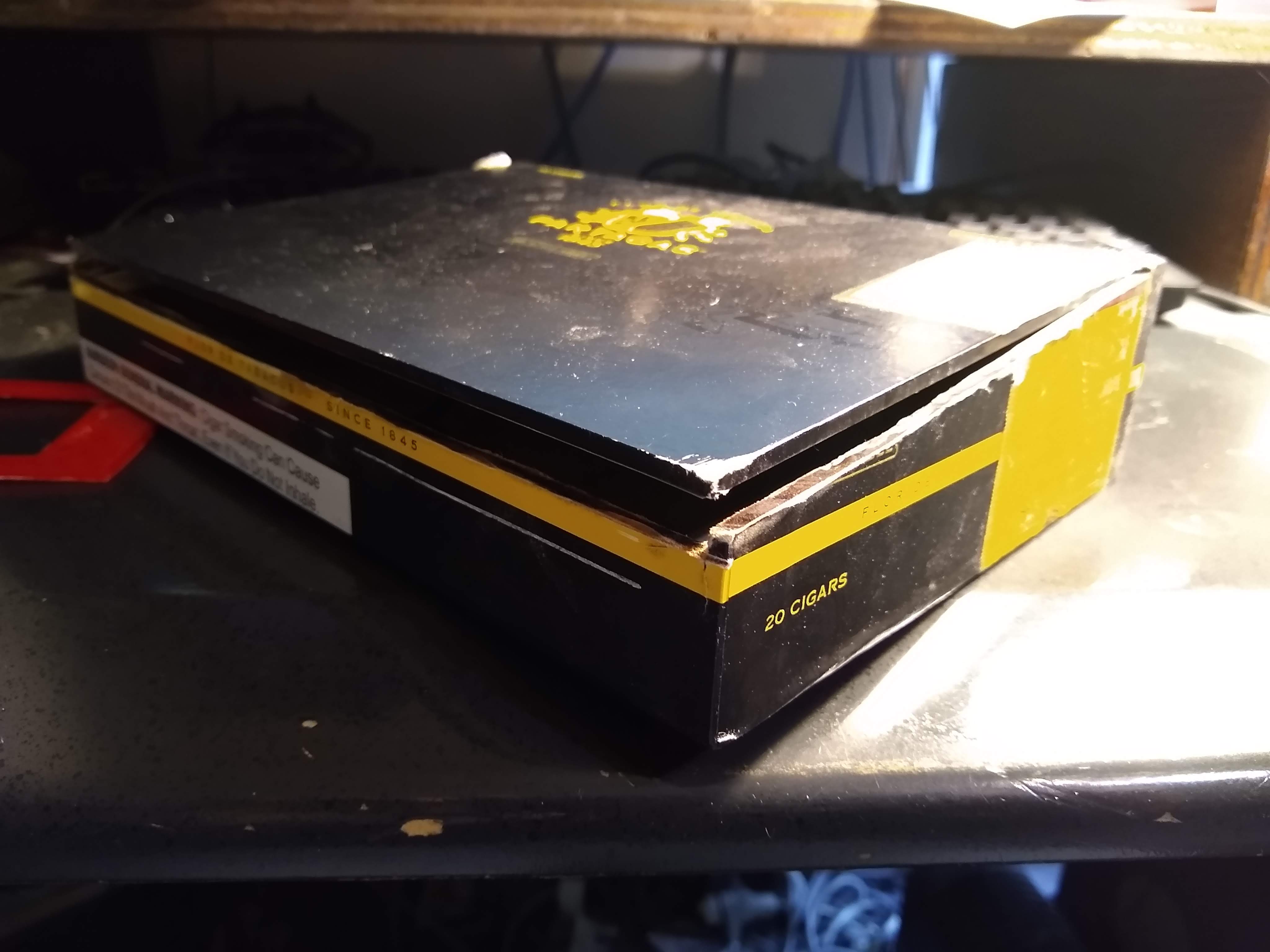
1 6 1/2 x 9 inch Cigar Box (I used a Partagas Black Gigante box, which I have a lot of. You can, of course, use a container of your choice, just make sure it's large enough and study enough to get stomped on).
-
Some light gauge, insulated wire.
In general, you can substitute and omit materials as you see fit. If you're willing to mount the Raspberry Pi in the corner of your container, you can omit the surface mount cables (although if you do this, you'll have to do something to accomodate the USB soundcard, which goes into one of those ports).
I've tried to recommend the best options based on my experiences, but be aware that there's some level of risk with all of this: please don't hold me responsible if things don't work out.
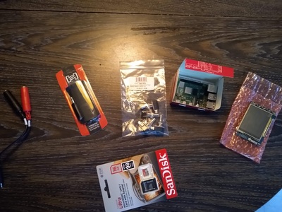
Pic of the first set of components I ordered (click to enlarge):

The Build
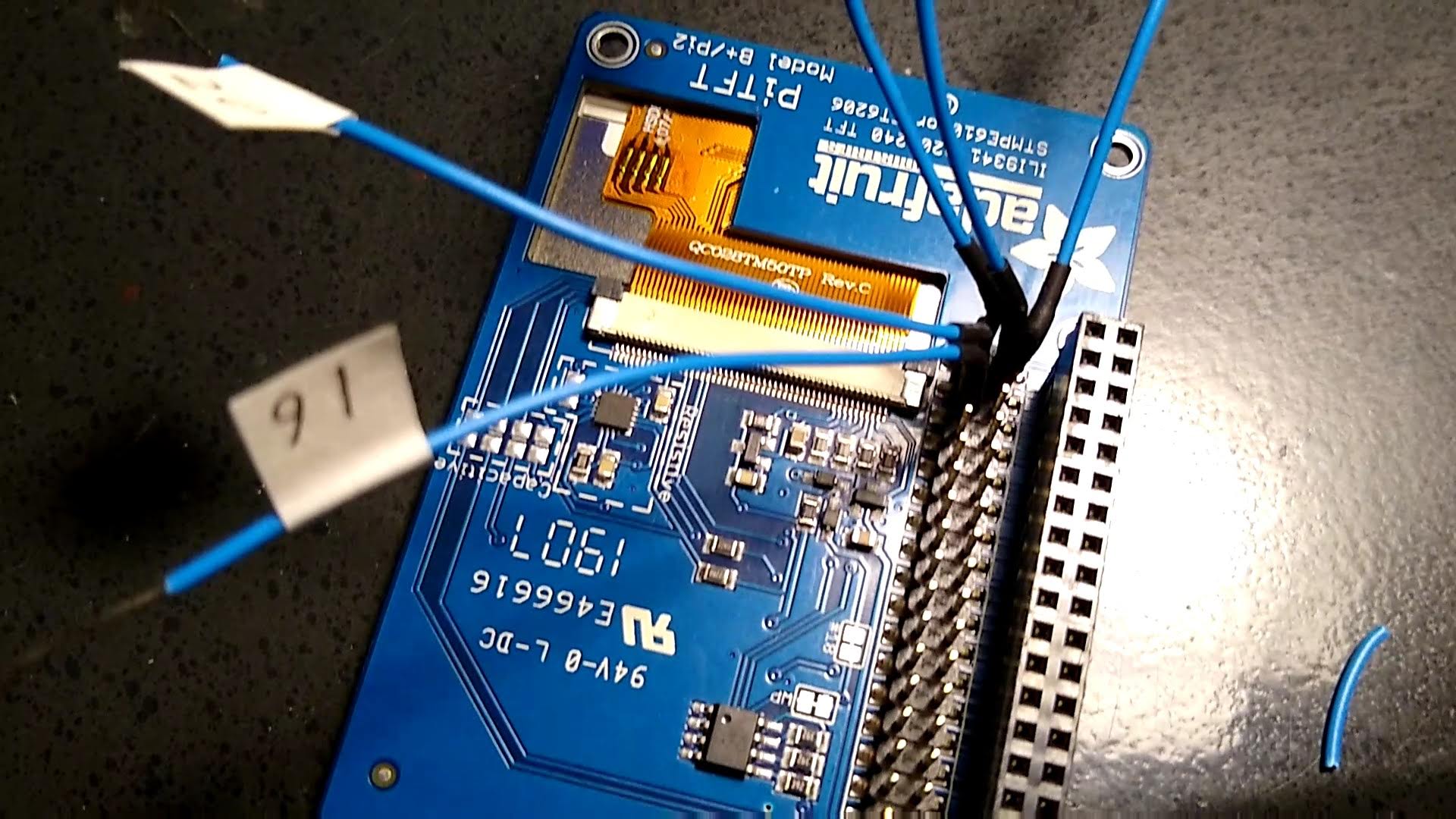
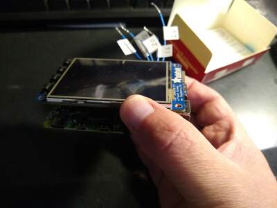
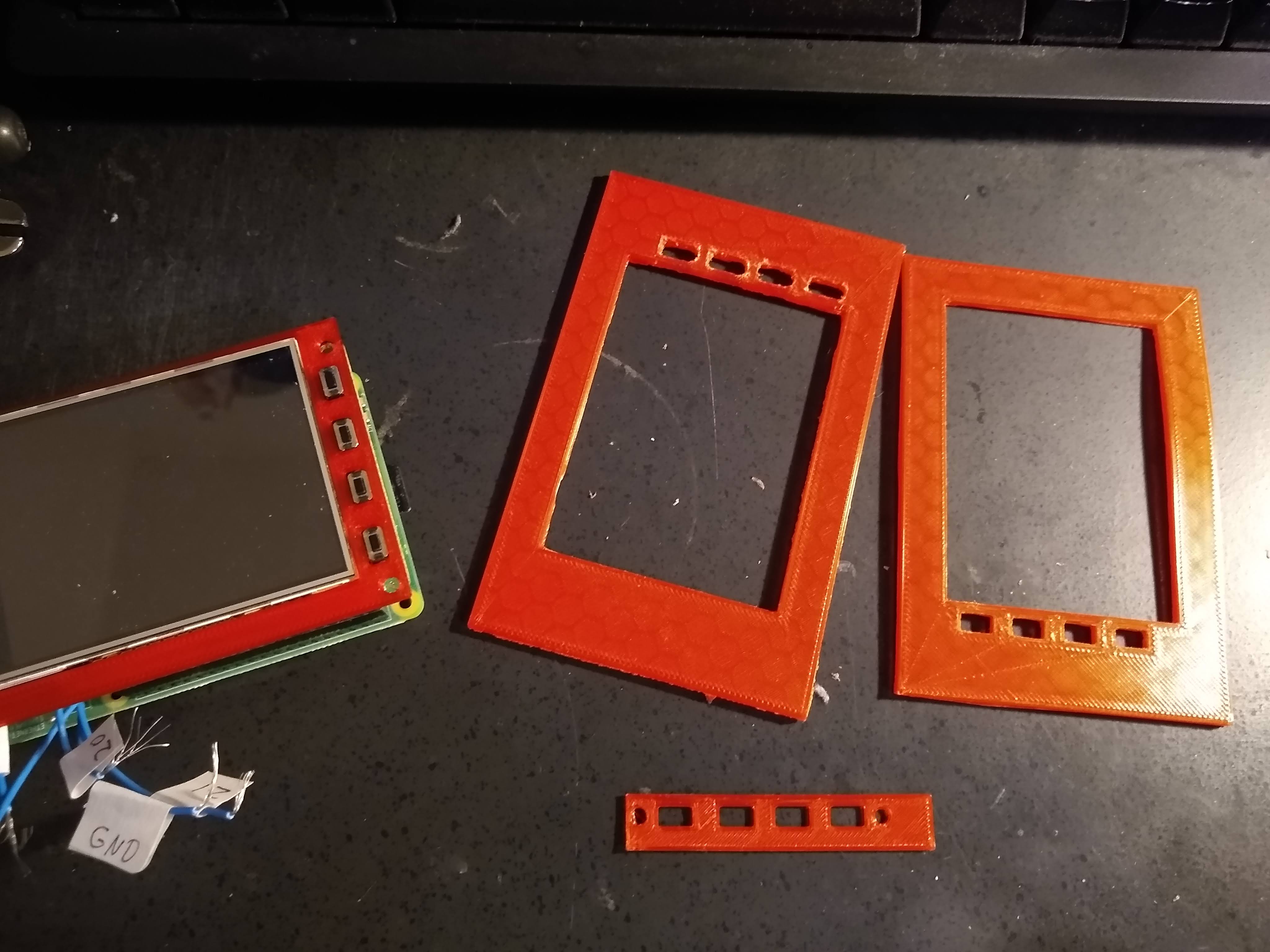
I started out by assembling the Raspberry Pi and its PiTFT hat. First, you'll want to attach the jumper wires to the GPIO pins (note: be sure to ground yourself before working with electronics. Touch some nearby metal or use a static pad. Static electricity kills components!).
The PiTFT sits on top of all of the GPIO pins, but it provides its own set of headers to them on the underside of the board (facing inwards towards the R Pi). The diagrams for the pi can be used for this. With a pair of wire cutters, cut the jumper wires so there's just the female end, then strip the remaining end.
I used GPIO pins 16, 20, 21, 26 and ground (these are header pins 36, 38, 40, 37 and 39, respectively) which constitute a nice cluster of the 5 pins at the inner end of header (make sure you don't use the pins closer to the edge as two of these are +5V and will likely fry your pi if they get wired to the GPIOs). Be sure to label your wires, you won't be able to see which pins they're attached to after the unit is assembled.
Videolink.
If you use a heatsink (recommended) you'll need to cut about a quarter of an inch off of the top of so that it will fit on the Pi's SOC without touching the PiTFT. I botched this quite nicely by trying to use first a grinder, then a hacksaw to cut the fins:
) 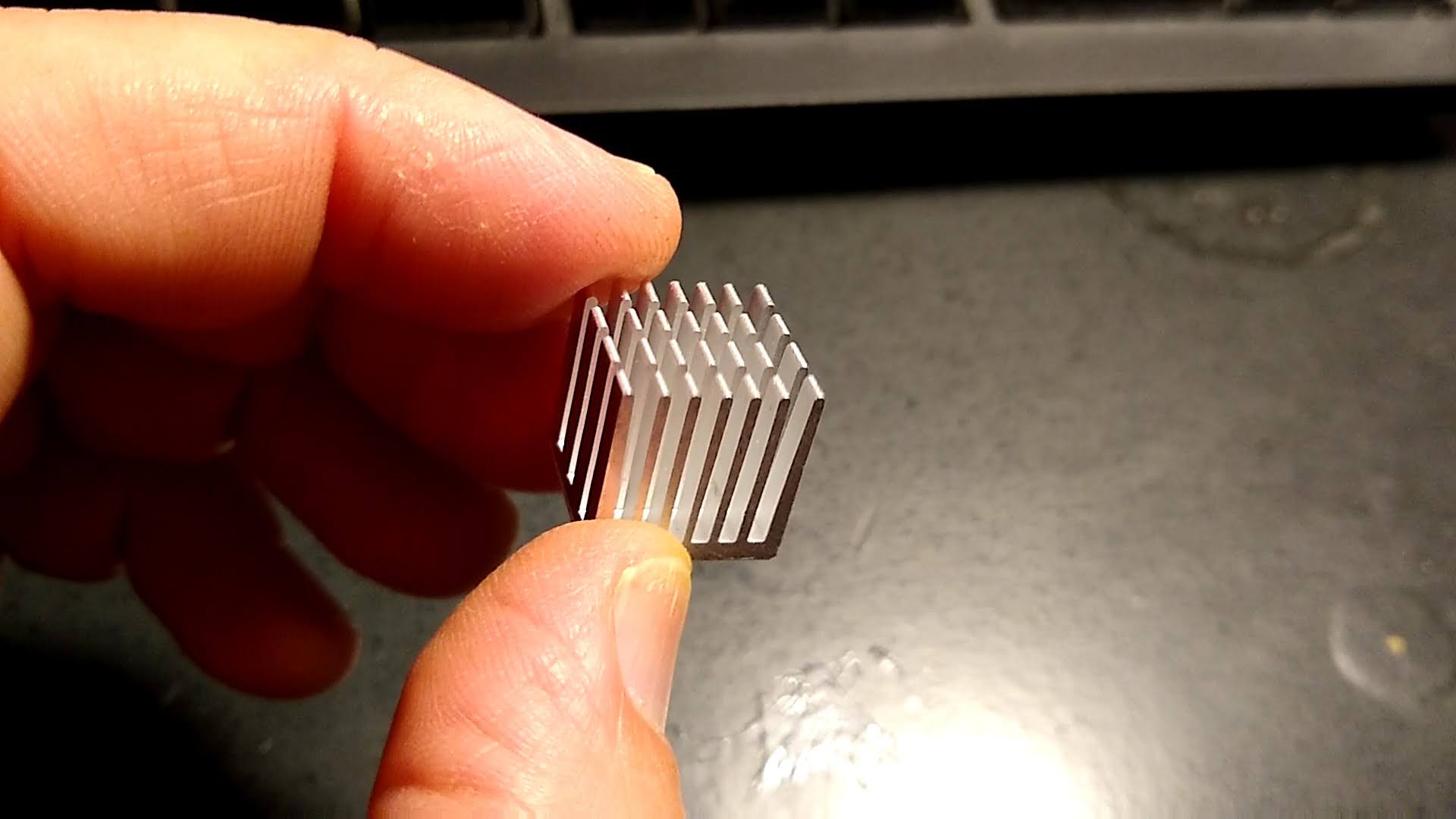
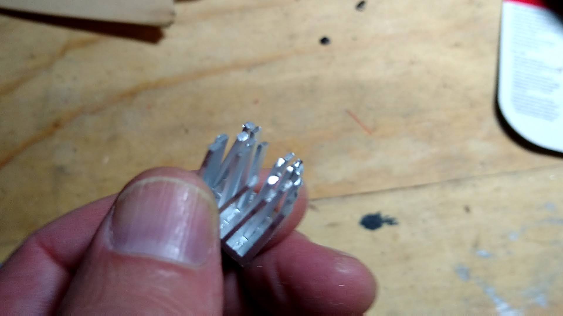
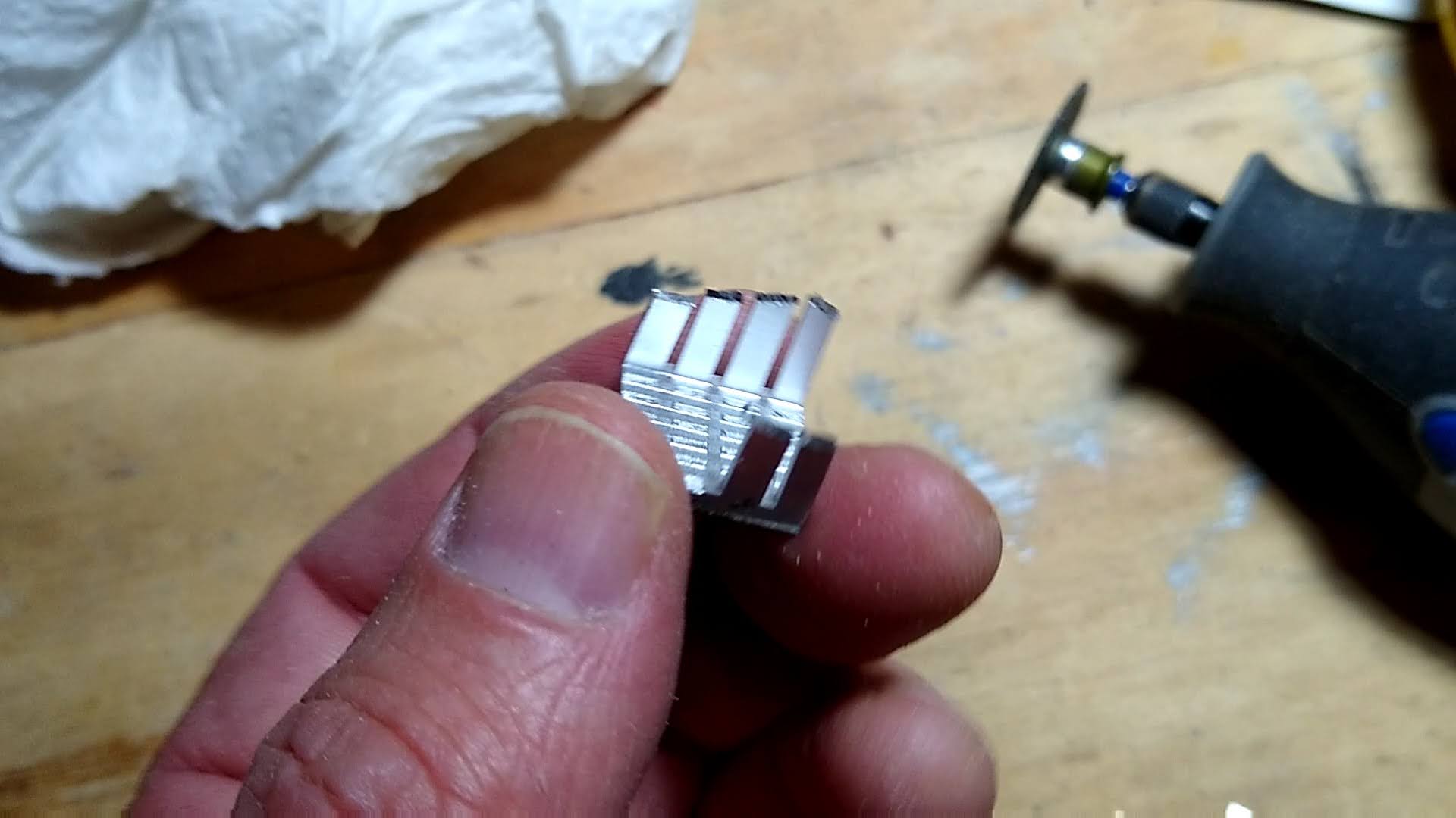
I had the most success with a dremel. It still ended up breaking some pins, but that may have been because they were already compromised from the grinder and hacksaw. YMMV. I ended up using the mutilated heatsink anyway, and have had no issues with overheating.
With a pair of pliers, bend the outer ends of the female sockets of the jumper wires after attaching them to give yourself a little extra space, and then, with heatsink and wires attached, press the PiTFT board onto the Raspberry Pi, feeding the wires out through the space between the headers and the USB ports.

At this point, you should be able to do some initial testing. Download a copy of Raspberry Pi OS and burn it onto your micro-SD card, then insert the card into the slot on the edge of the pi and power up.
You may have some problems with your touchscreen driver (I did). When you power up, you should see the desktop on the screen and touching the screen should reposition the mouse pointer. If this is not the case, see my notes under the header "Setting up R-Pi". You may also need to find some instructions for changing the screen orientation if it doesn't work with the way you plan to install it (I have mine oriented with the ports facing the back and the left of the device and the microswitches to the right, IIRC I had to reorient the display by 180 degrees).
At this point, you can focus on the case. I cut up a cigar box with a dremel, initially cutting the side panels diagonally to create a nice beveled effect that would work well for stomping on the footswitches, and a rectangular opening large enough to accomodate the touchscreen and buttons without too much extra space:

As it turns out, with a small amount of bevel (2 1/8 inch back, 1 1/4 inch front, in my case) the lid will still reach to the front of the unit.
If you're using something like a cigar box, you'll probably want to cut a pair of side-braces out of pieces of wood (I think mine were about 1 inch wide). These will give the unit more stability and also give you something to screw the lid down onto. I had to cut a rectangular dip into the left one to provide space for the cables and an opening for two of the USB ports.
Now drill 4 large holes into the front top of the unit, about 5/8 of an inch from the front. These are what you will mount the buttons into. You can, in fact, install the buttons at this time.
If you have a good feeling for what you are doing, you may also now want to cut holes in the case for the stereo output sockets, mono input socket, ethernet, power, and USB ports. I put everything but the two USB2 ports on the back of the unit and put the two USB ports in a stack on the left (remember that one USB3 port will be reserved for the sound card). When cutting the apertures, be sure to leave enough space for the mounting screw brackets between them.
The next step for me was to design and 3D print the faceplate. This was challenging, as the tolerances of the screw-holes surrounding the PiTFT were more precise than I could easily measure with my calipers. I ended up printing a number of smaller, thinner pieces in order to get a pretty close fit on the positions of everything:
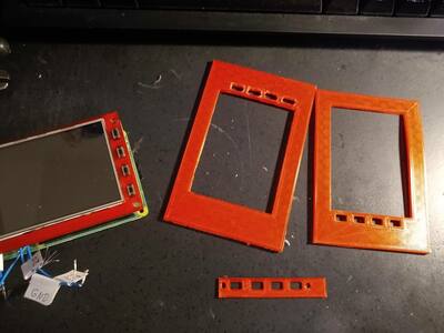
Once I got a pretty good fit, I printed out the thicker final unit (it's still a bit buckled on the bottom, I didn't get the screw positions quite right). My 3D files for the final product are in the repository (see the "Faceplate" files, in general I've provided both the FreeCad source files and the STL files generated from them for the 3D models).
Drill 4 holes through the corners of the faceplate and case so that everything is lined up nicely and then screw the faceplate onto the PiTFT/Pi 4 core unit. You can now mount the combined faceplate and core assembly onto the lid of the unit.
At this point, you can solder the wiring from the switches to the 5 jumper wires from the unit. For each button, solder a length of wire from one terminal of the switch to the jumper wire for the corresponding GPIO (from left to right, these should be GPIOs 16, 20, 21 and 26) and then solder a wire from the other terminal to the "ground" jumper wire (this last part is a bit tricky, I recommend twisting all 5 wires together as best you can before applying solder to all of them). Use electrical tape to insulate the soldered joints connecting to the jumper wires so they can't touch each other or any other exposed metal.
After attaching the soundcard, you should now have a somewhat functional unit:

Now would be a good time to install the software so that you can test
everything out before going any further. Attach the stereo Y adapter to the
headphones jack on the soundcard and attach the mono adapter to the microphone
jack via the mono extension cable. You'll also want to hook up an ethernet cable
to the pi (either that or a keyboard and monitor so you can setup wifi) and then
follow the instructions in my notes on
installing all of the software components. Installing the Cables
At this point, you'll need to cut some holes for the output ports if you haven't already (see earlier discussion). Most of them should be mounted with screws into their apertures. However, the adapter plugs don't have screw mounts (there are screw-mountable versions of these if you'd prefer a stabler design that involves a bit more soldering and confidence in your ability to avoid signal interference). For these, you'll want to 3D print some brackets. Mine are in the repo in the "PlugBracket" and "DoublePlugBracket" files. They get mounted to the floor of the unit as shown below:

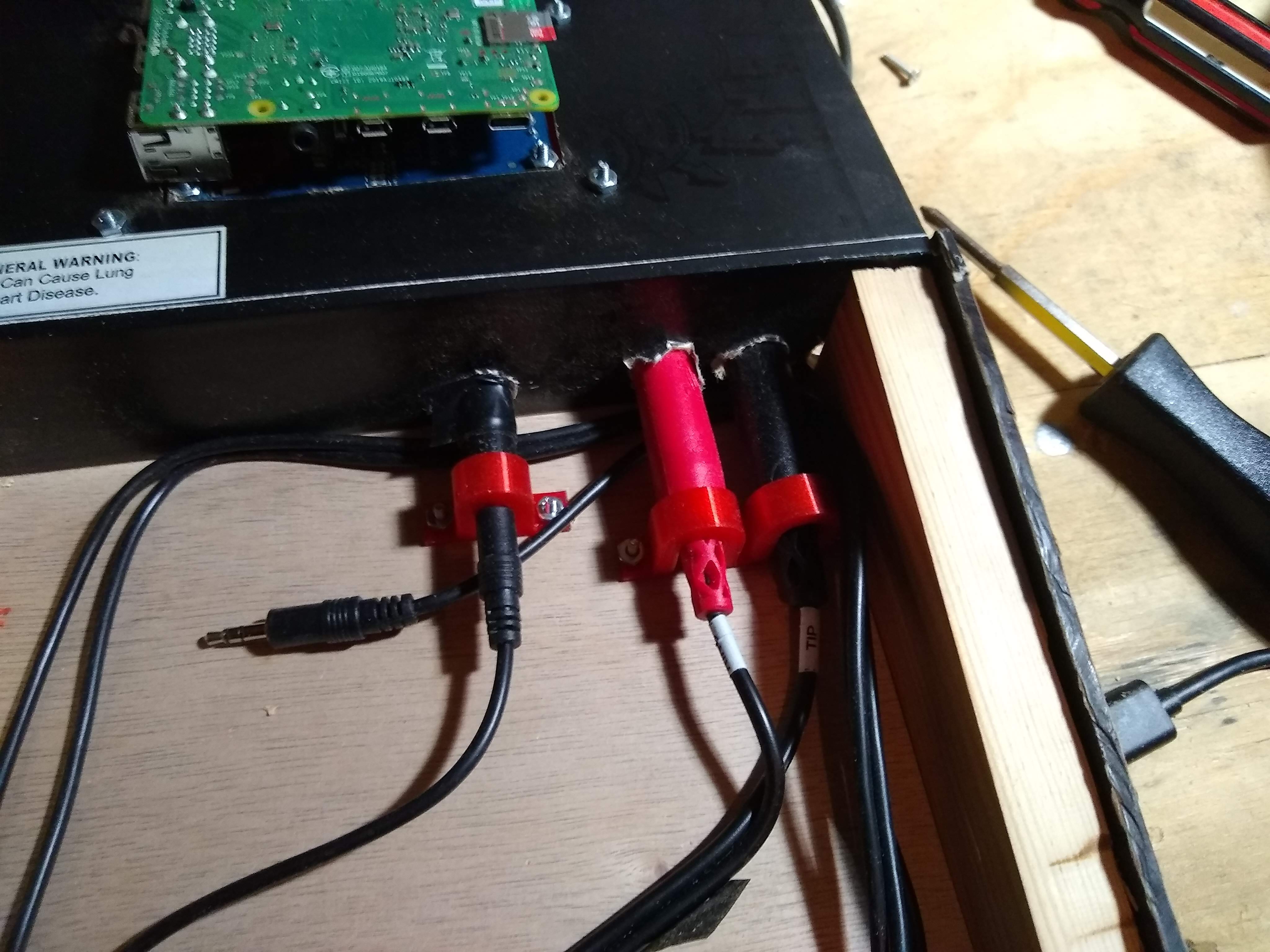
The adapters should fit snugly into the holes in the back of the unit (I wrapped them in electrical tape to get a nice snug fit) and the brackets should press against them to hold them firmly (you'll be plugging and unplugging from these quite frequently). I ended up wrapping the (overly long) mono extension cable under the plugs and around the floor of the unit.
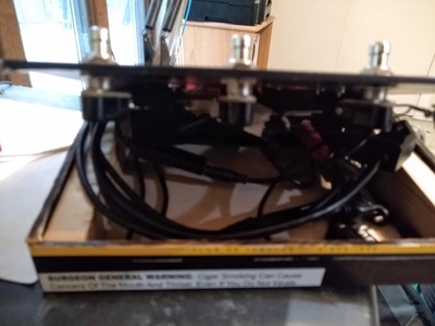
At this point, assuming everything is working fairly well, you can install the extension cables for power, ethernet and USB. The extension cables are fairly rigid, and the inside of the unit ends up being rather cramped. You'll want to circle the USB2 port cables around once and feed the other cables around and to the back.

Do another test run, verify that all of the ports function (I hooked up a midi keyboard to the USB ports and verified that I could see the device with aconnect).
Finally, you can close the unit. I pressed down hard to squeeze the cables in
and used a pair of screws in the front of the lid to mount the lid down to the
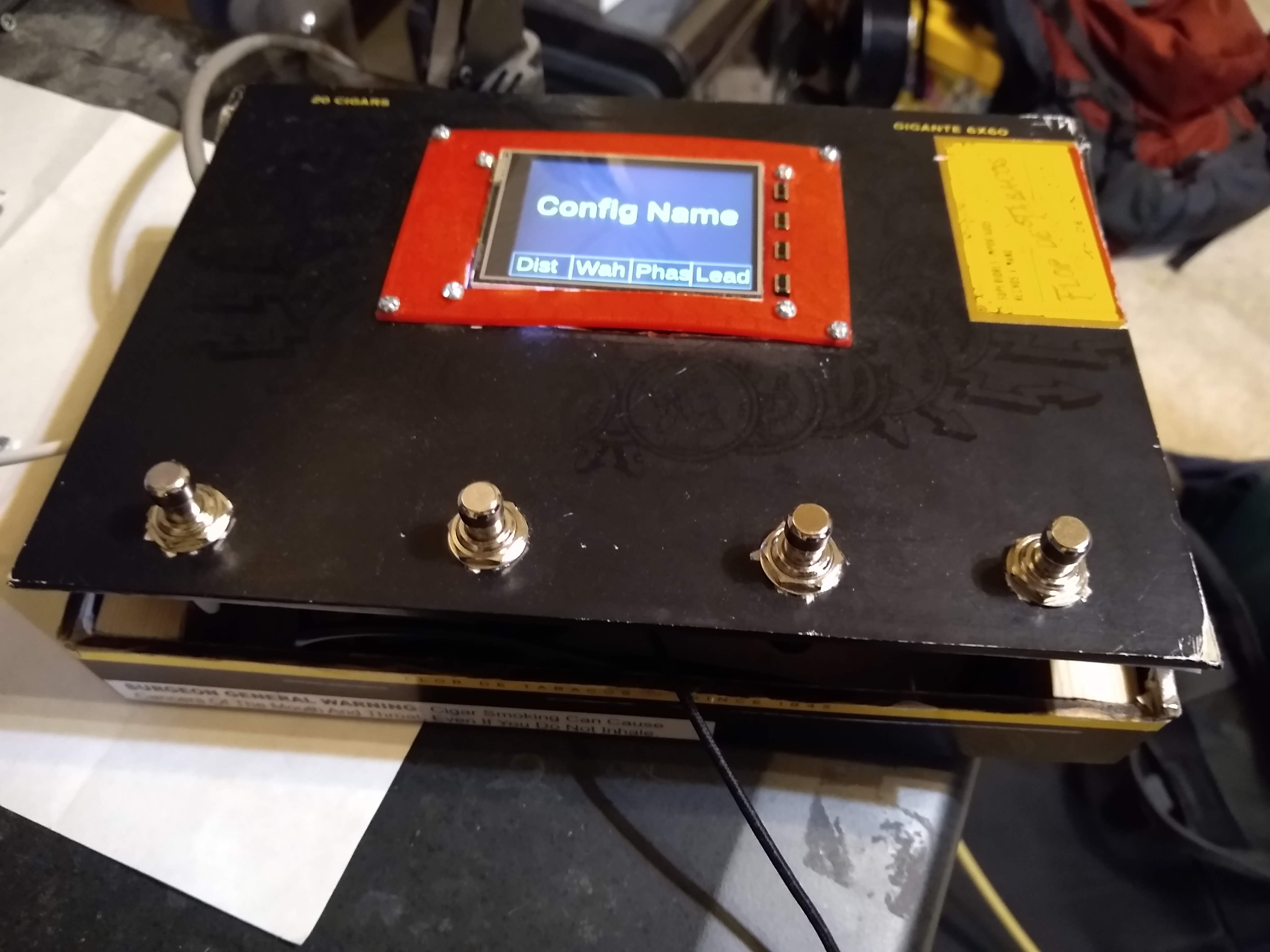
wooden supports. Basic Operation
The unit is currently configured by modifying the custom.py file. Effects chains are organized into "configurations," one of which is active on the system at any time. In general, the footswitches let you toggle effects on or off or select between different programs. The micro-switches to the right of the screen let you navigate around the interface (top button toggles between the main screen and the menu list, the next two buttons move the selection up and down and the bottom button selects an item). From the main menu, you can access the list of all configurations, bring up a tuner, restart the control software or cleanly shutdown the pi.
In most configurations, pressing both of the two rightmost footswitches also
brings up the the configuration list. At this point, the two left-most
footswitches navigate up and down, the third footswitch selects a configuration
and the rightmost returns you to the main screen at the current configuration. Final Thoughts
I've been using the unit reqularly at home and at jams (sadly, I've only had the opportunity to play one real performance over the past year due to of the pandemic, but I did use the pidal for that). It has proven itself to be quite stage-worthy, both hardware and software, and it's fairly awesome to be able to play using a piece of equipment that I built myself.
I mentioned earlier that the Hosa mono adapter should be avoided for this project. I tried two of them in the course of development and in both cases, they didn't fit the 1/4 inch guiter plug snugly enough. The result was that any physical contact with the unit, however slight, would result in a loud popping noise (amplifed and distorted by whatever effects were loaded at the time). The Pig Hog adapter, while not perfect in this respect, works a lot better.
This is not to denigrate Hosa's products: in general, I've had no complaints about their adapters and, in fact, their stereo Y cable (used for the output ports) has been perfectly fine.
I had some concerns about the unit overheating. As stated earlier, I'm using a rather butchered heatsink and the unit is totally closed, with no real ventilation to speak of. That said, I've been keeping a close eye on the temperature of the unit and even after extensive use, I haven't seen the core temperature go above 70C. Obviously, this is likely to vary with the amount of computational load that you put on it so you may want to keep an eye on this if you're really piling on a lot of effects and making heavy use of all cpu cores simultaneously.
Finally, the software on the unit is under active development. I'm currently transitioning to mod-host for most of my newer effect chains and hope to add a UI that I can control from a browser on my phone. I will likely remove Rakarrack at some point (I love it, but it uses 40% of a CPU even in headless mode even with nothing connected to the jack ports, and is challenging to configure) and possibly even Guitarix as well, assuming I can replicate all of my Guitarix effects chains adequately. Customizing the effect pipelines isn't really documented at this point, although this is currently a high priority for me.
In closing, I hope you've found this interesting. If you end up doing
something similar, please drop me a line and let me know how it worked out for
you! Similar Projects
-
The Electo-Smash - A tiny unit based on a little pi-zero!
-
The Pedal Pi - Next generation of the Electro-Smash?
-
The Pi-FX - A Guitarix-oriented unit.
Contact me and I'll list your project.